
@ENPC – Sept. 2019 – C. Douthe, X. Tellier, K. Mam
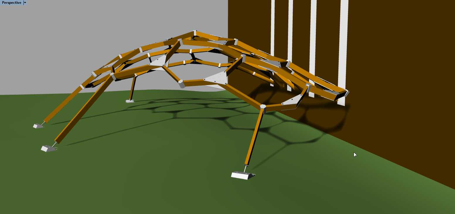
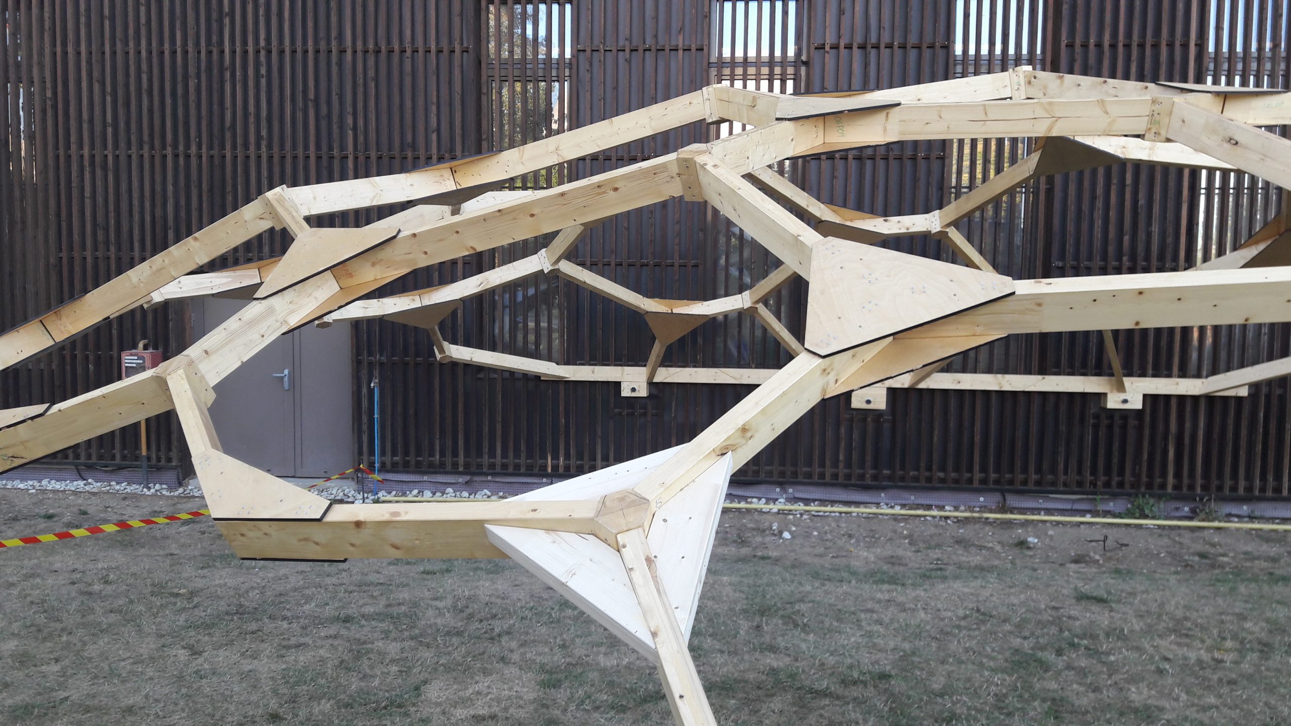
This intensive workshop is dedicated to double curvature structures and the discovery of their design and manufacturing methods. Through the realisation of 8m-span wooden caravel mesh, the 2019 edition illustrates the research on constructive geometry of the group which masters here all the stages of the project: from the proof of convergence of the optimization method to the realization and the assembly through the sizing of the structure to Eurocodes.
Features of the 2019 edition
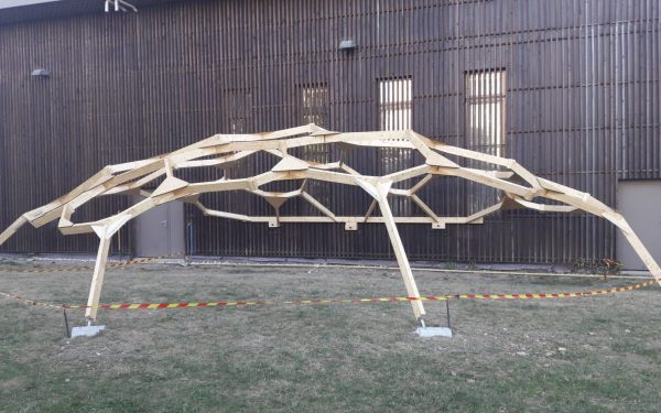
Context
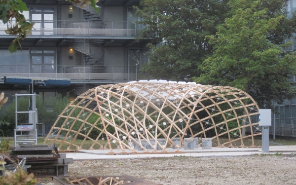
This wooden pavilion was assembled during the building freeform workshop of September 2019. It illustrates the research of the group on constructive geometry which masters here all the stages of the project: from the proof of convergence of the optimization method to the realization and the assembly through the sizing of the structure to Eurocodes. The entire process is integrated within a parametric design tool (Rhino) which allows easy consideration of the different constraints: mechanical (f.e. related to the angle of the screws with the wood grain), geometric (f.e. related to the positioning of singularities on the surface) or manufacturing (f.e. related to the risk of collision between the clamp of the robot and the saw plate).
Partnerships
The general approach is partnership-based and multidisciplinary and combines multiple skills and fundings:
- Two research laboratories: the Navier laboratory (UMR 8205) and the LAMA (UMR 8050), involved in two labex MMCD and Bezoult,
- The Civil Engineering department at the Ecole des Ponts, the ENSAVT Master “Matière à penser”
- Three manufacturers: the carpenter Simonin SA, the number one of fixation Würth France and the Start-Up HAL Robotics.
The one-year-sized pavilion will be part of the exhibition organized for the AAG 2020 conference.
Key figures
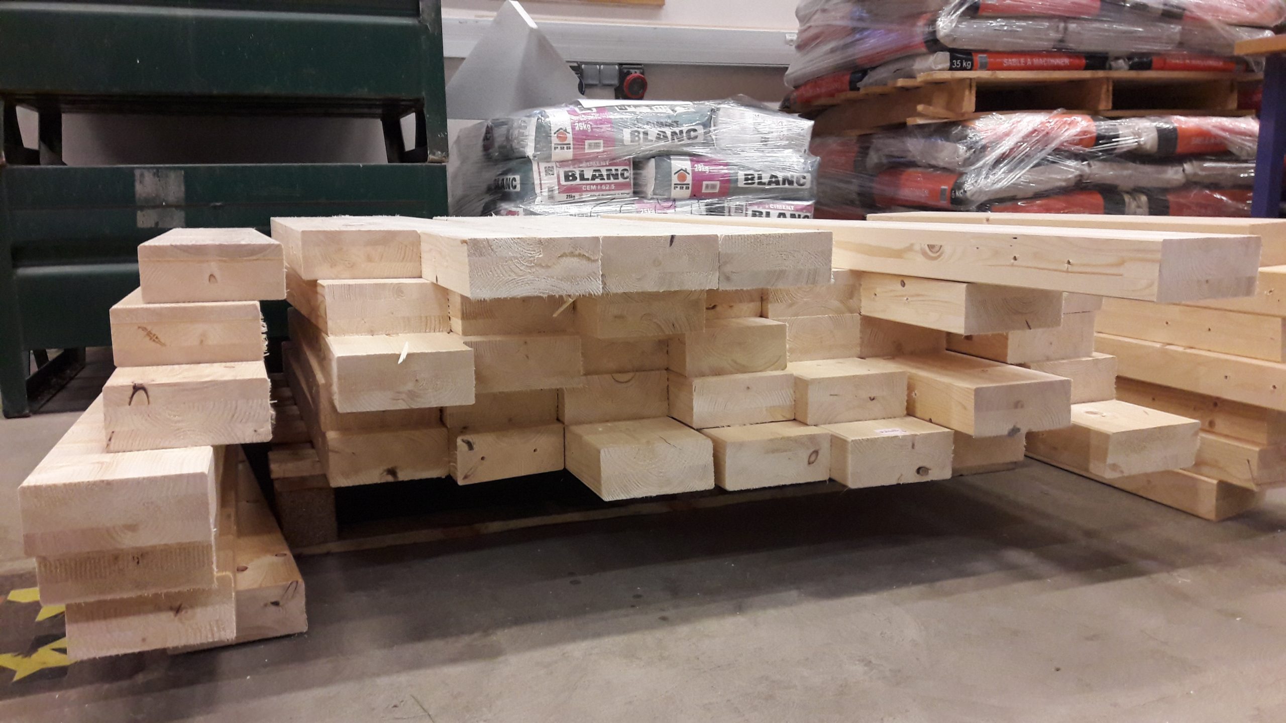
- 82 beams in GL28h (60×140)
- 4 poles (60×140)
- 26 space nodes (180 screws 8×240)
- 26 planar nodes (ie 2400 4×50 screws)
- 200kg of concrete for foundations
References :
- PFE Mathieu Lerouge
- Article SN Applied Sciences
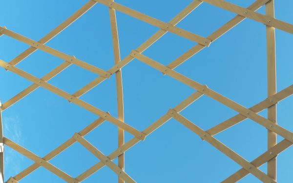
A robust generation method
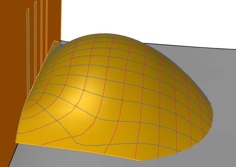
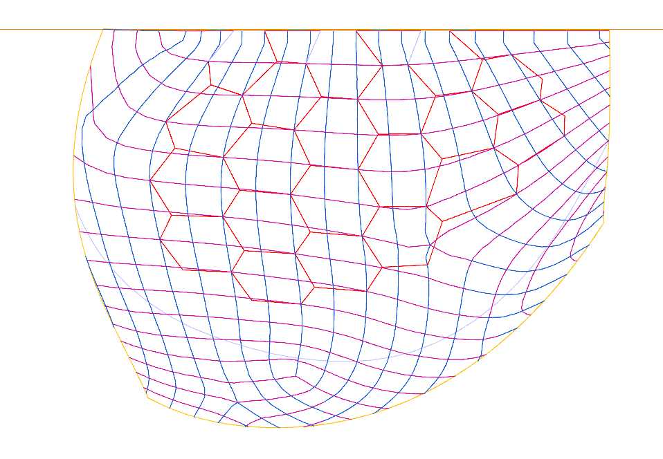
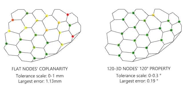
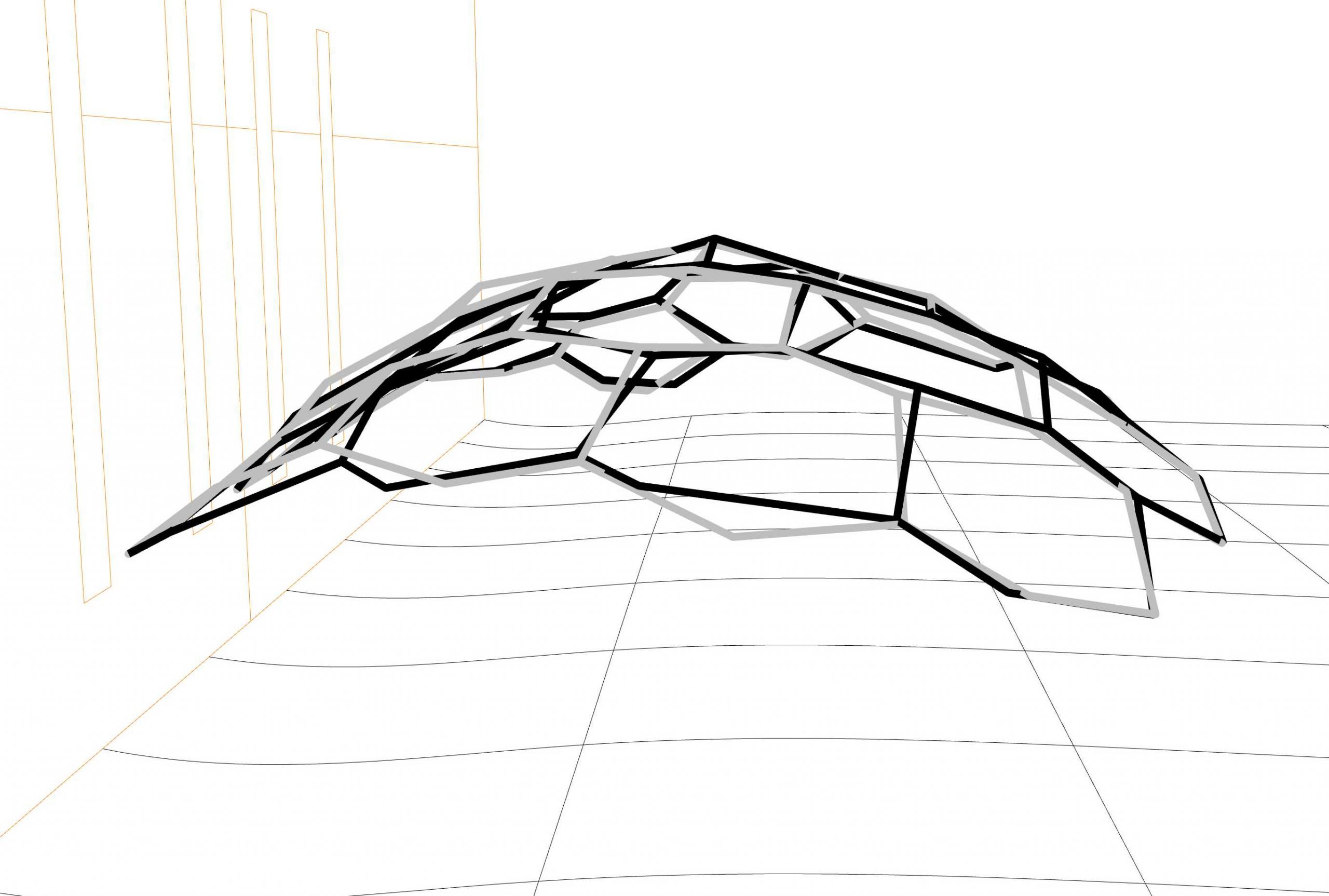
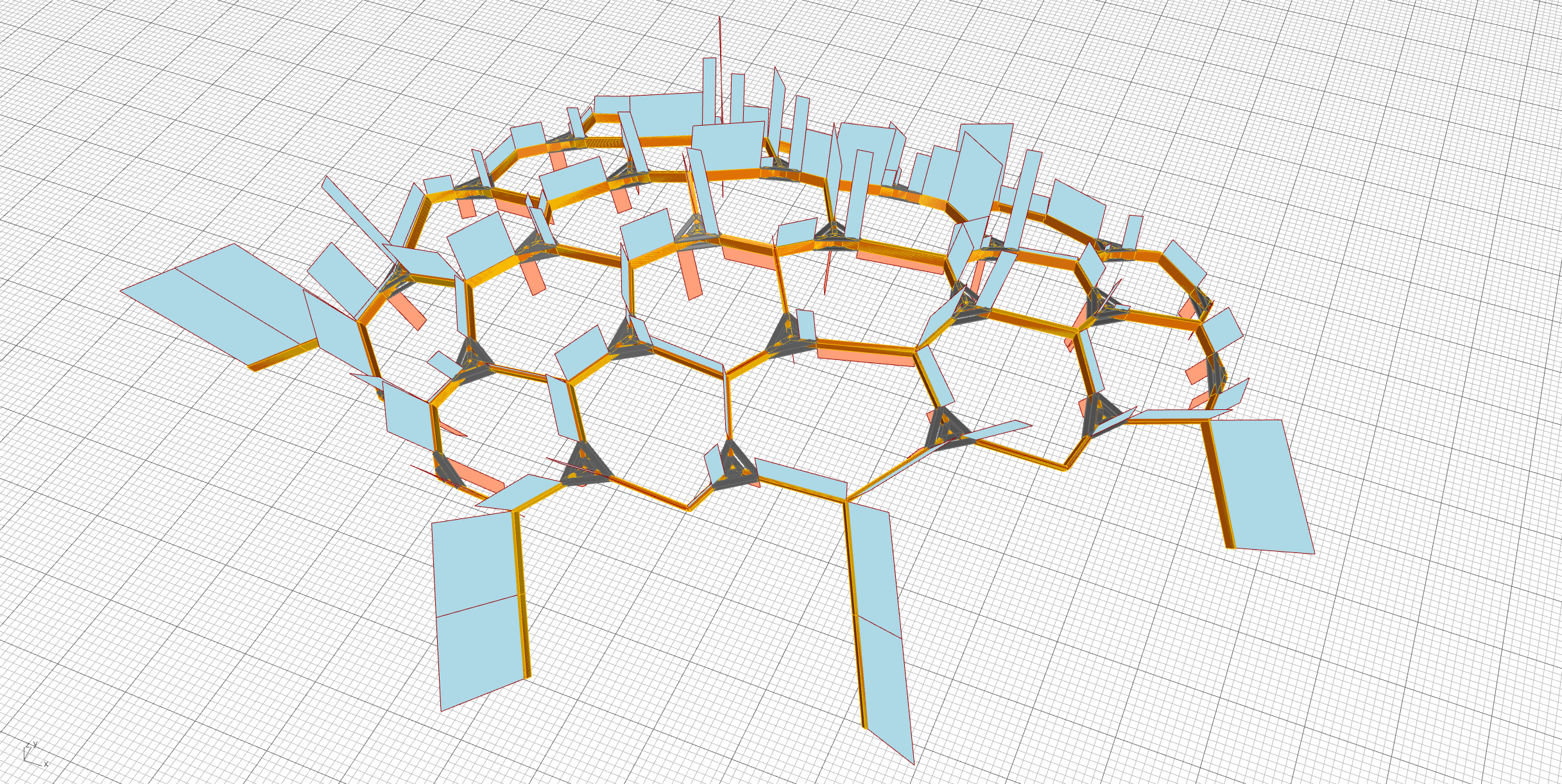
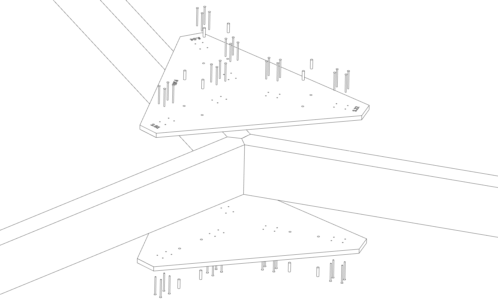
The structure of the pavilion is based on an original principle of surfaces meshed by hexagons built on the principal curvature lines of curvature. It then uses the property of 2-colorability of this mesh to separate the nodes in two groups, one formed by planar nodes whose only degree of freedom is the angle between two successive beams, the other formed by nodes at 120 ° whose only degree of freedom is the angle formed by the beam with the axis of the node in each of the three 120 ° planes. If the existence of such a mesh is demonstrated when the size of the elements is small compared to the curvature of the surface, it is generally necessary for reasonable sizes of beams to resort to an optimization step which is here carried out using custom goals/constraints implemented in kangaroo2 to achieve a general accuracy of less than a millimeter.
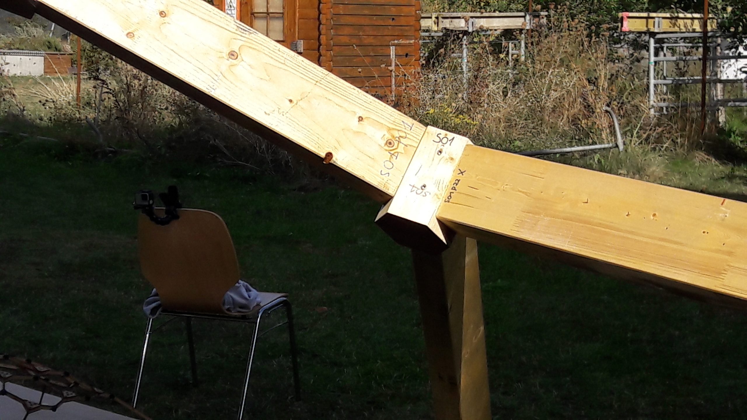
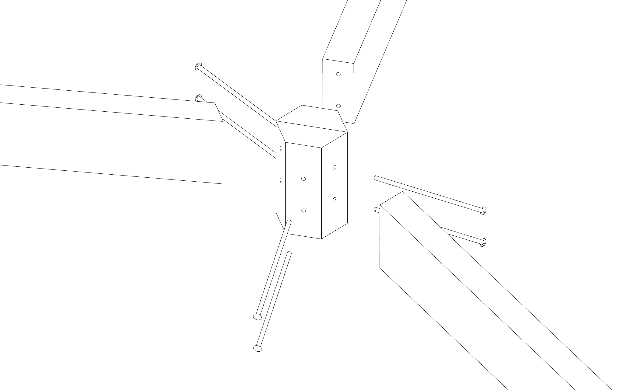
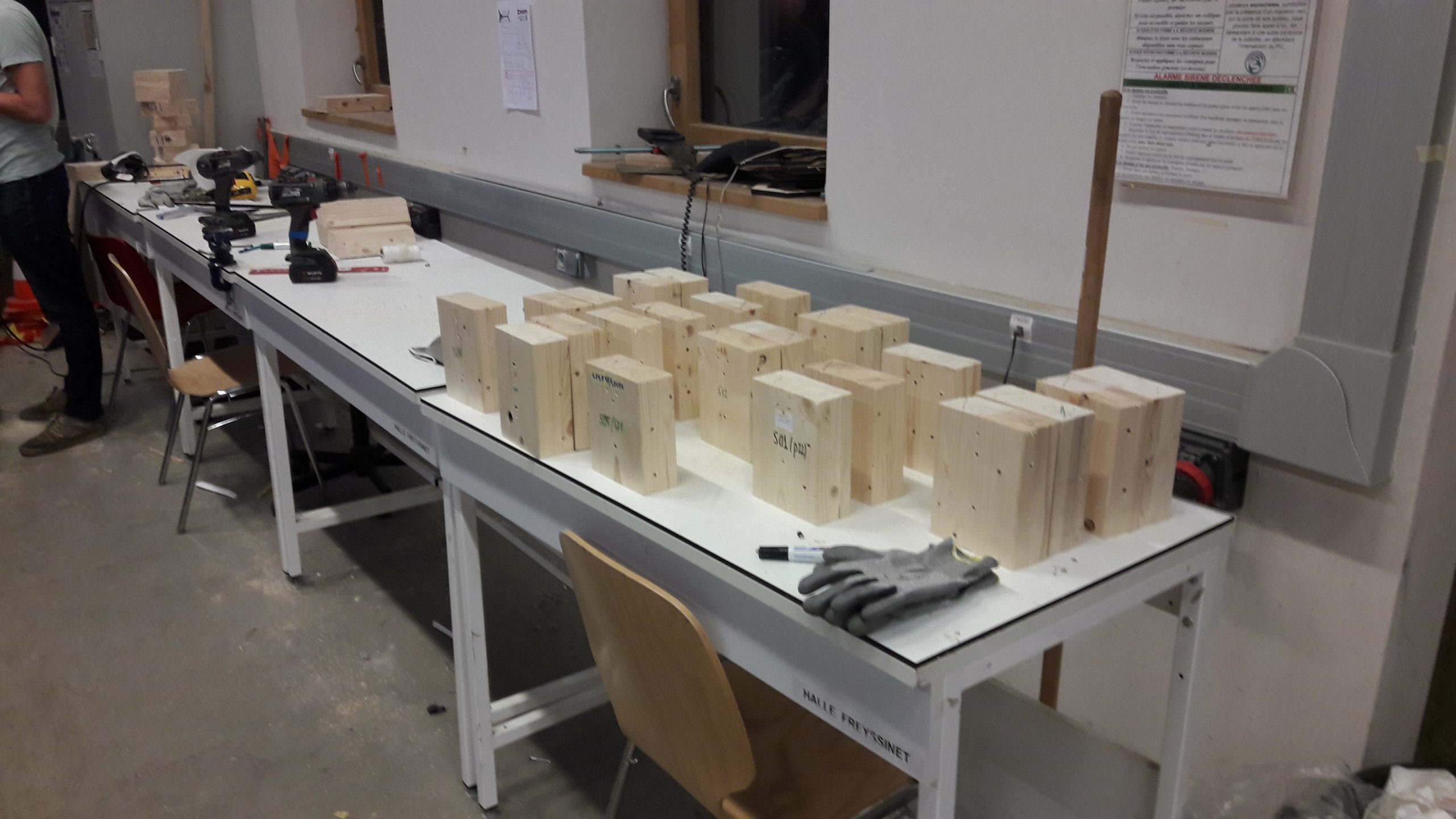
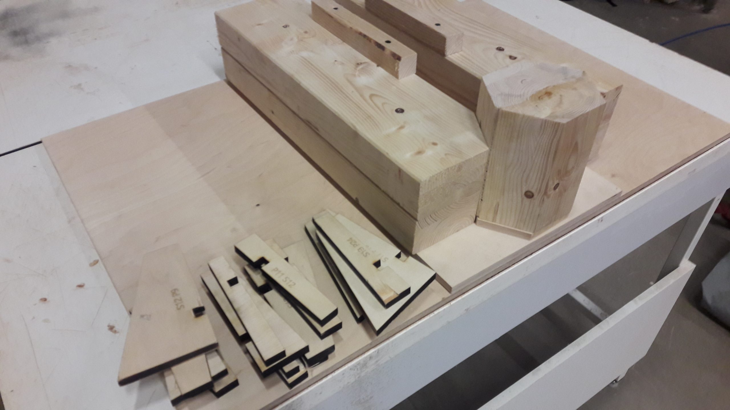
Detailing
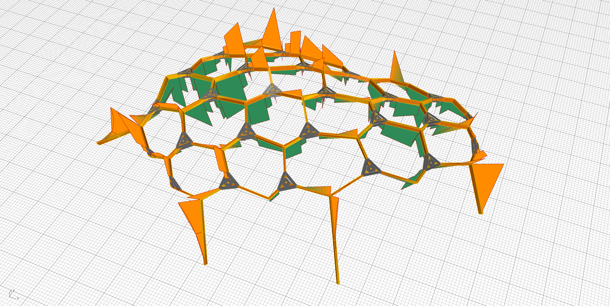
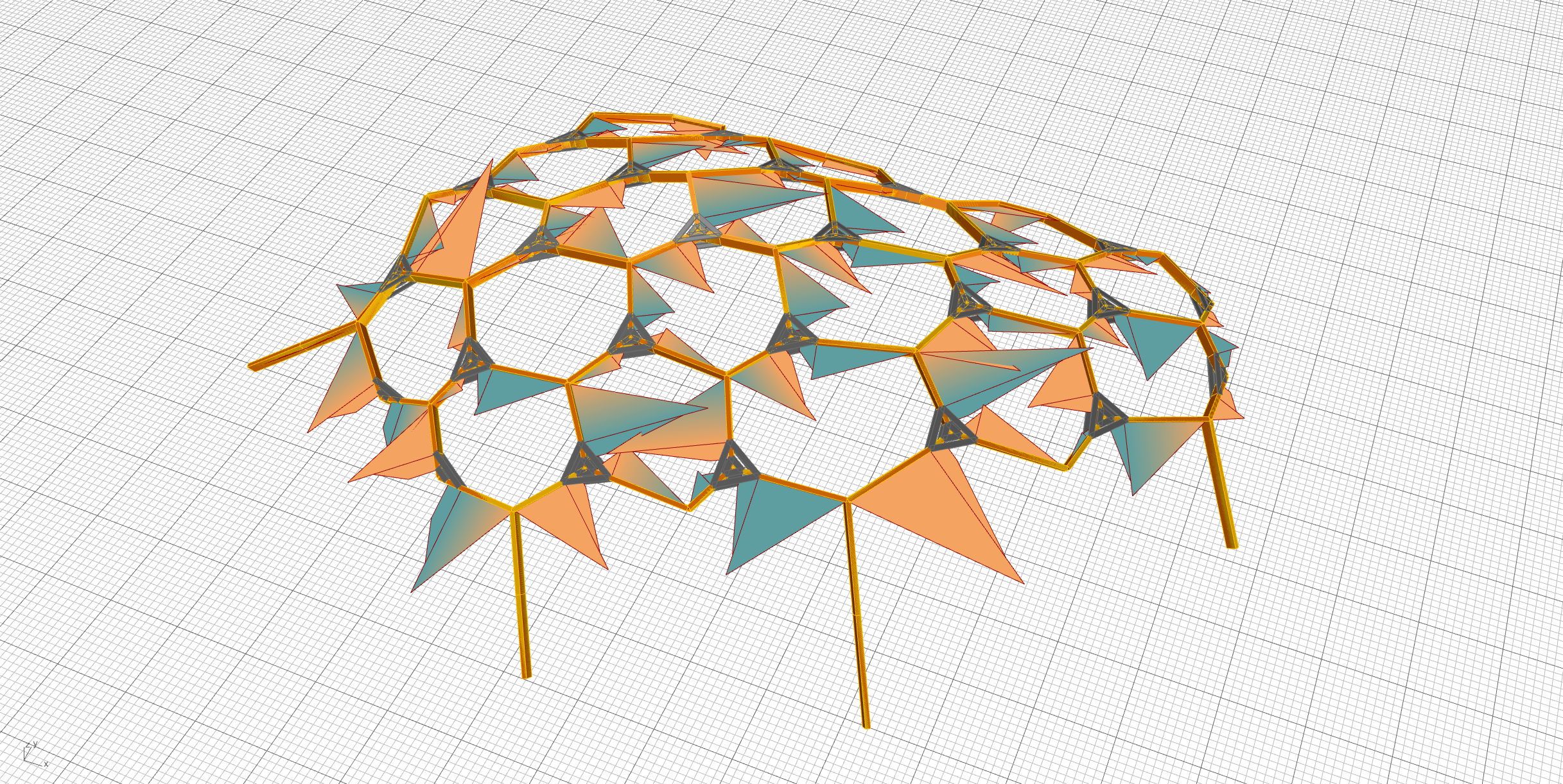
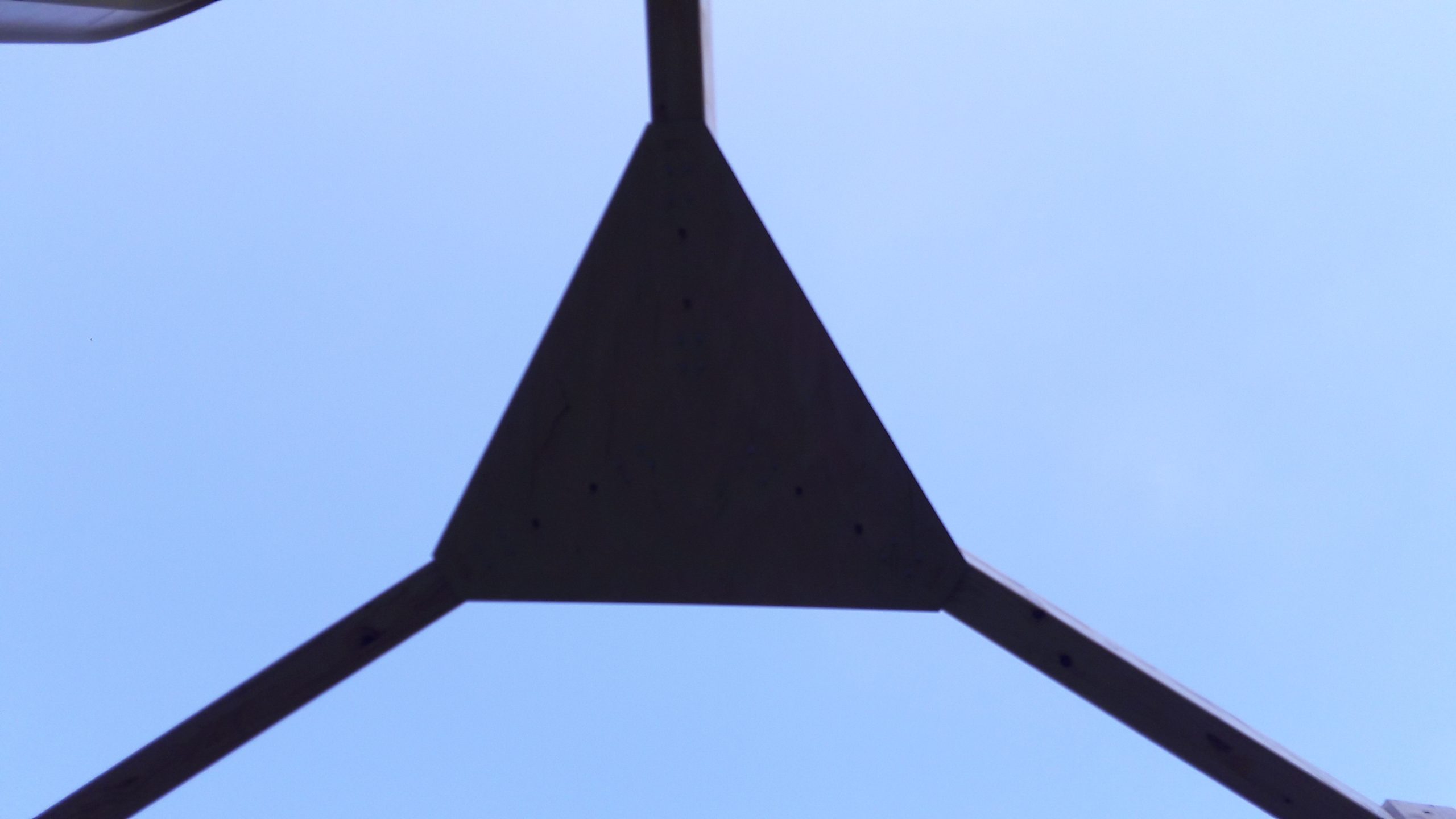
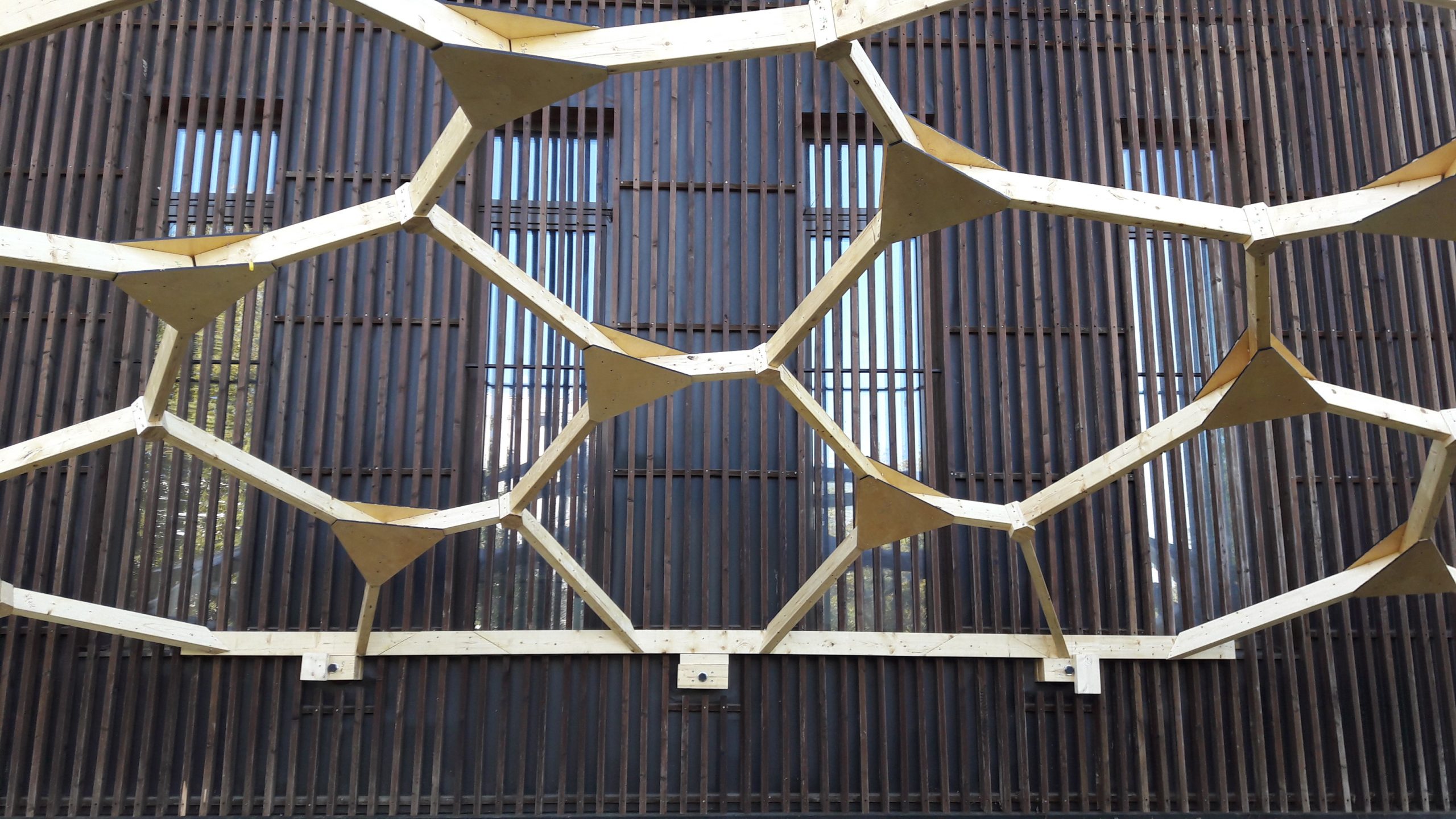
There are two main details in this structure. The first, called 120°-node, consists of two half hexagons glued together, through which the beams are screwed. The average planes of the beams, defined by the beam centre line and the nodes axis (which are here without torsion) form between them angles of 120 °. The angle between the screw and the wood grain as well as the spacing between the screws (8×240) are chosen to maximize the bending capacity of the joints (based on the technical agreement of ASSY screw by Wurth, which is the manufacturer and partner of the workshop). The second, called flat node, consists of two pre-drilled and laser cut 12 mm plywood plates that sandwich the end of the beams and thus feature a flexible embedment. It is the flat nodes that brace the structure.
120° node
Flat node
Supports & posts
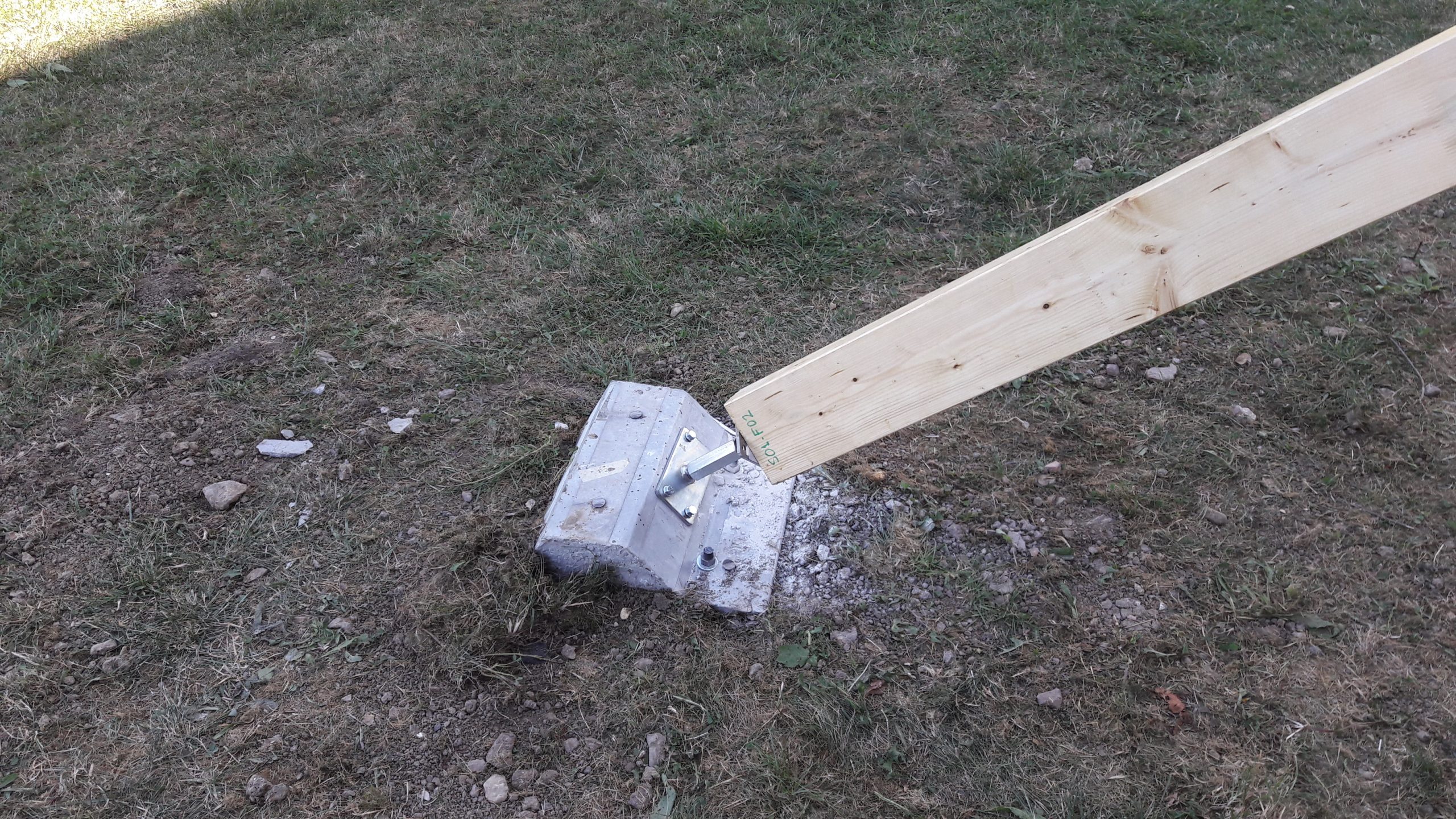
The main detail is adapted for posts in order to block the rotation of the post head around the axis of the node. This connection is made using standard gusset made of the same sections as the beams but arranged in a plane perpendicular to the node axis. These gussets frame the 120°-nodes and are therefore all identical. On the ground, the feet of the columns are hinged in three directions using a standard steel foot screwed into a concrete block cast into a custom mold that allows to control the orientation of the post. On the other side of the structure, a continuous straight beam is bolt in 3 dedicated slot along the building.
Manufacturing
The parts were manufactured using the build’in platform and based on technical developments of previous years. For the beams, we use a 6-axis robot on a track which seizes the beams on a shelf and which, by successive passes on two tables equipped with a circular saw and a drill, comes to make the necessary oblique cuts and the pre-holes that will guide the screws in the desired orientations. All the beams are different in length and angle. All the orientations of the holes are different as well. For the most pronounced angles, the size of the clamp did not allow a through cut, so that it had to be completed by hand. The panels are cut with the help of the laser cutting machine (from ENPC makerspace) which also opens the pre-holes for the screws as well as a keying and guide set for the geometric setting of the flat nodes.
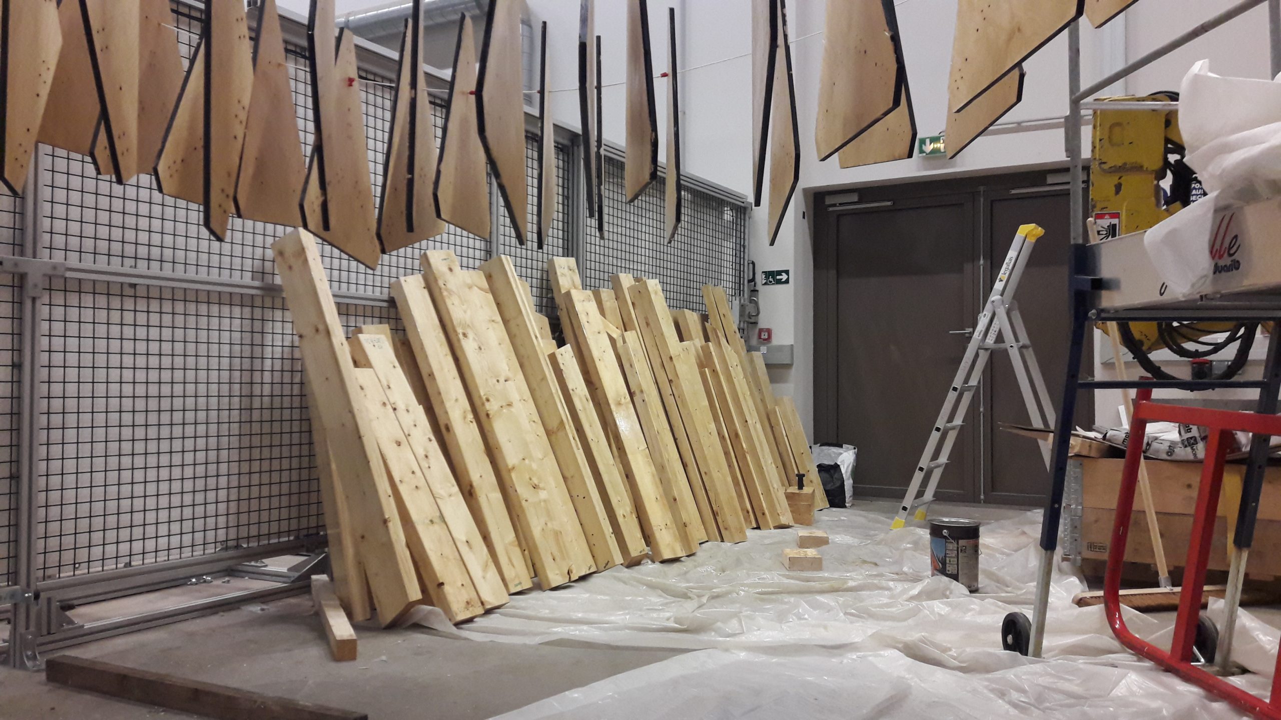
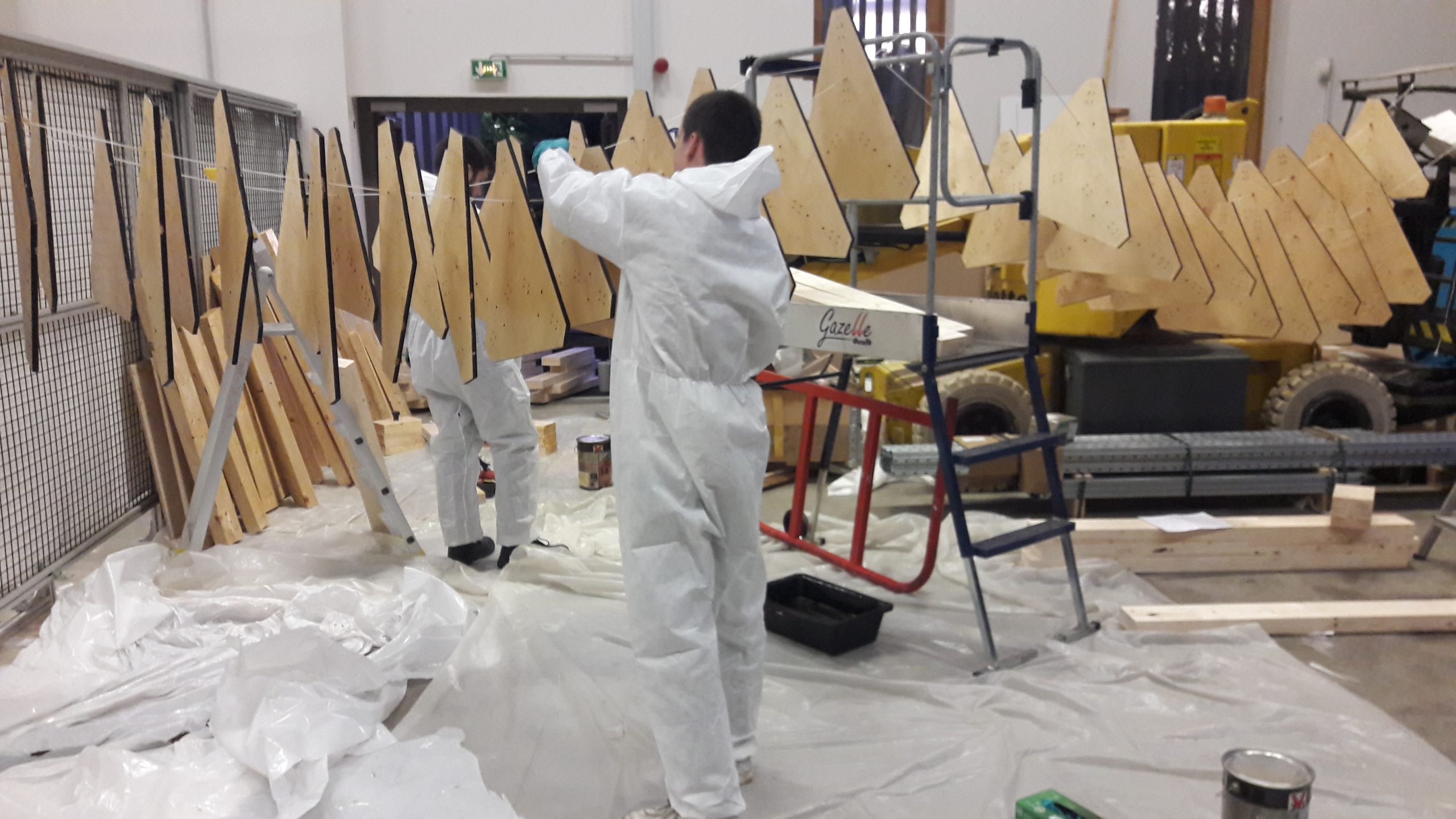
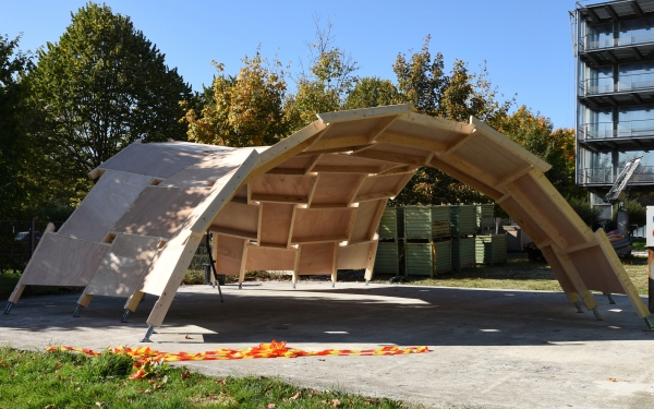
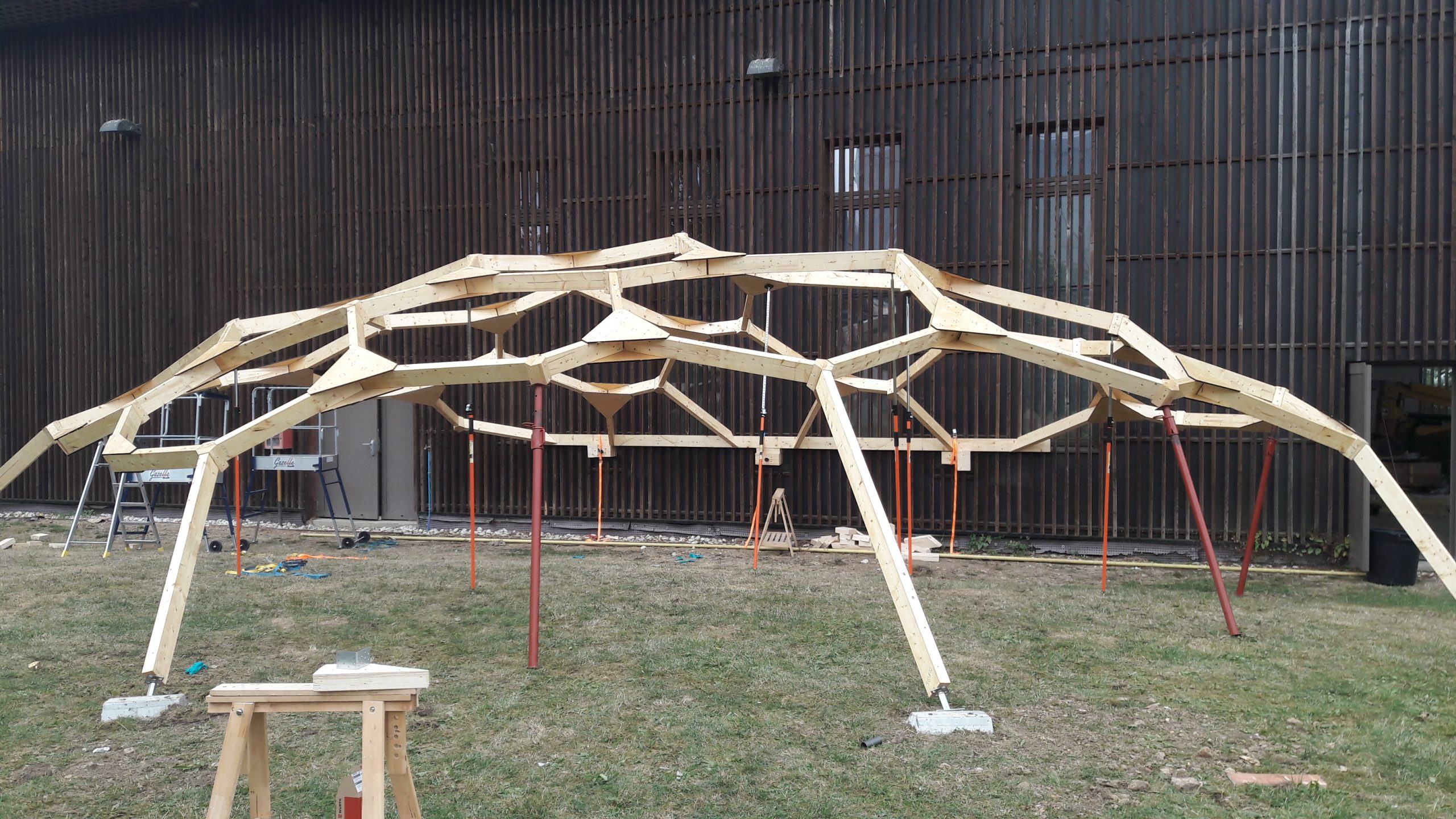
Mounting
All the parts of the structure (panels, beams and hexagonal knots) were stained before assembly for greater durability. Next, two pre-assembly workshops of 120 ° nodes were set up because their accuracy is easier to guarantee in the workshop than on site. At the same time, another team was assembling the 6.4m long beam, anchoring the foundations, installing the anchors to the wall in the reservations provided for this purpose. The actual assembly begins then, gradually from the edge beam, on the ground and then on struts until the establishment of poles. No particular difficulty was encountered, except for a single plane node which could not be aligned with the corresponding beam and which therefore had to be screwed with a defect of the order of 5 mm at the end of the panel.
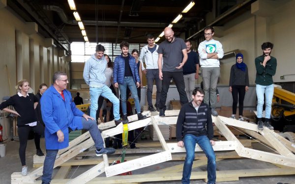
Loading tests
The complete survey of the geometry built is planned in the coming months as well as loading tests. These structural tests will complement those already carried out in the laboratory on the connections and which made it possible to characterize stiffnesses and resistances of the main assemblies. These results will of course be compared with the numerical models of the structure in order to understand the amplitude of the imperfections of the realized object as well as their influence on the general behavior of the structure.
Acknoledgements
To all the students from Ecole des Ponts Paristech and the ENSAVT School of Architecture :
ALLE Capucine, ALVAREZ PEREZ Ana, AVELLANEDA CUFRE Juan Cruz, BARREIRO Joanna,BOUTILLIER Romane, CAQUOT Octave, CARDONA LOPEZ Sofia, CAVERO GUILLEN Marta, CONVERT Antoine, de ROMANETde BEAUNE Amance, DE ROSSI Serena, DIACO Leonardo, DREVETON Matthias, GALICKI Piotr, GENARO João Victor, GILSON Adèle, LEPRISÉ Thomas, OLALQUIAGA VARELA Ignacio Maria, OLIVEIRA Quentin, QUINTANAL SAGÜES Luis, RIOL CEPEDA Maria, ROYER Benjamin, SARMANHO CASTANHO SAVIO Gabriel, SILVA ARAUJO Marcos Vinicius, SJAAI Mossaab, TISSOT Juliette
To all those who were there for supervising their work and preparating this incredibly enthousiasting workshop:
Stephen CONORD (Würth France), Hocine DELMI (Navier), Léo DEMONT (Navier), Cyril DOUTHE (Navier), Tristan GOBIN (HAL Robotics), Mathieu LEROUGE (Navier), Koliann MAM (Navier/Elioth), Thibault MANDALAZ (Würth France), Romain MESNIL (ENPC), Loïc SIMONIN (Simonin SA), Xavier TELLIER (Navier).
